Inspect the wall system
Segmental precast retaining units for repeatable wall construction along rail, road and constrained infrastructure corridors.
Engineered wall segments for rail, road and constrained infrastructure corridors.
Repeatable precast units turn a long, changing alignment into a coordinated manufacturing and installation sequence.
Segment classes respond to retained height, chainage, foundation steps, curves and interfaces defined by the approved design.
Soil, surcharge, groundwater, bearing, sliding, overturning and drainage must work together as one engineered system.
Survey control, safe lifting, joint geometry, staged backfill and drainage preserve line, level and long-term performance.
Segmental precast retaining units for repeatable wall construction along rail, road and constrained infrastructure corridors.
Map retained height, curves, steps, crossings and interfaces at every relevant chainage so the segment schedule reflects the real corridor.
Use the engineering design to group units into practical height and geometry classes while keeping manufacture and erection efficient.
Small set-out or level errors accumulate over long runs. Foundation tolerances and segment joints must be inspected continuously.
Delivery order, crane reach, temporary stability and backfill sequence should follow the corridor workfront and safety plan.
Connect segment marks, production inspections, dispatch records and as-built chainages for a traceable linear asset.
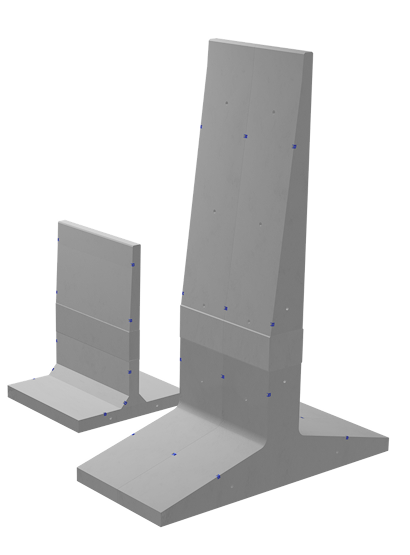
The interactive model could not load. The product reference remains available.
Application cards describe typical use contexts, not automatic suitability. The project team must confirm geometry, loading, exposure, standards and interfaces for the actual location.
Coordinate the product with adjoining construction, access, drainage, safety and the approved project details.
Coordinate the product with adjoining construction, access, drainage, safety and the approved project details.
Coordinate the product with adjoining construction, access, drainage, safety and the approved project details.
Coordinate the product with adjoining construction, access, drainage, safety and the approved project details.
Coordinate the product with adjoining construction, access, drainage, safety and the approved project details.
Coordinate the product with adjoining construction, access, drainage, safety and the approved project details.
These supplied catalogue spreads are shown as references for product understanding. Click any panel to inspect it at full size. Approved project drawings remain the controlling documents.
Segmental retaining units divide a long wall into manageable repeated elements. That improves serial production and corridor installation, but does not remove the need for a complete retaining-wall design. Each segment, joint, foundation and drainage detail must respond to the retained soil and project geometry. The six inputs alongside form a practical pre-production checklist.
Record the requirement on the current approved drawing or schedule and coordinate it with affected disciplines.
Record the requirement on the current approved drawing or schedule and coordinate it with affected disciplines.
Record the requirement on the current approved drawing or schedule and coordinate it with affected disciplines.
Record the requirement on the current approved drawing or schedule and coordinate it with affected disciplines.
Record the requirement on the current approved drawing or schedule and coordinate it with affected disciplines.
Record the requirement on the current approved drawing or schedule and coordinate it with affected disciplines.
Precast gains programme certainty when survey, design, production, logistics and erection are treated as one connected workflow rather than separate purchases.
Convert survey and technical inputs into an agreed basis.
Freeze the product geometry, interfaces and required checks.
Complete factory production and documented inspection.
Coordinate safe delivery, lifting, line and level on site.
Close interfaces and retain the required handover records.
Controlled moulds and curing improve repeatability, while site teams concentrate on preparation, lifting, interfaces and safe completion. Final performance still depends on the complete engineered system.
A catalogue-backed characteristic to evaluate against the project programme, design basis and installation method.
A catalogue-backed characteristic to evaluate against the project programme, design basis and installation method.
A catalogue-backed characteristic to evaluate against the project programme, design basis and installation method.
A catalogue-backed characteristic to evaluate against the project programme, design basis and installation method.
Twelve practical questions covering selection, engineering, production, handling, installation and documentation.
They support repeatable production, manageable lifting and phased installation while accommodating changes through an engineered unit schedule.
The wall profile and foundation steps are designed by chainage, then matched to approved segment classes and transitions.
The catalogue shows a bullet-train project reference, but each rail project still requires its authority approvals, clearances, loading and engineering review.
Use accurate survey control, verified foundation levels, defined joints and progressive line and level checks during erection.
Project-specific dimensions and interfaces can be reviewed before manufacture, subject to engineering, mould and production feasibility.
Share the latest drawings, quantities, application, levels, loading or hydraulic inputs, site location and required programme.
Yes. The GLB and catalogue explain the product; they do not replace the consultant-approved structural, geotechnical, hydraulic or electrical design.
Yes, after the unit schedule and technical scope are frozen, manufacture and dispatch can be coordinated to the agreed workfront sequence.
Use only approved lifting points, unit weights, equipment and method statements. Stable dunnage, stack height and ground conditions must be planned.
Applicable drawings, material records and inspection documentation can be discussed for the confirmed product and project scope.
Existing levels, dimensions, utilities and tolerances must be surveyed and incorporated into the approved interface details before manufacture.
No. The interactive model is for product understanding. Only the latest approved production and project drawings govern manufacture and installation.
Share the drawings, quantities, site, loading or hydraulic inputs and programme for a product-specific technical discussion.